Introduction
The world we live in is a three-dimensional space. The eye, the most important perception organ of human beings, can not only provide colorful color information for human beings, but also form a sense of distance in the brain, so that we can perceive a three-dimensional world. Since the birth of the first CCD image sensor in Bell Laboratories, in the past few decades, machine vision and digital imaging technology have made great progress, giving tremendous energy to all walks of life. People's lives, industrial automation, aerospace and other fields have begun to be widely linked with image and visual technology.
The field of machine vision has experienced the evolution process from analog to digital, from static to dynamic, and from monochrome to color. The current 3D vision technology is to improve the dimension of machine vision by presenting stereo images in front of people, which can meet the application scenarios that are difficult to achieve in the past 2D vision, such as Face ID, mobile phone, VR/AR, industrial vision and other directions, and start a new visual revolution in all walks of life!
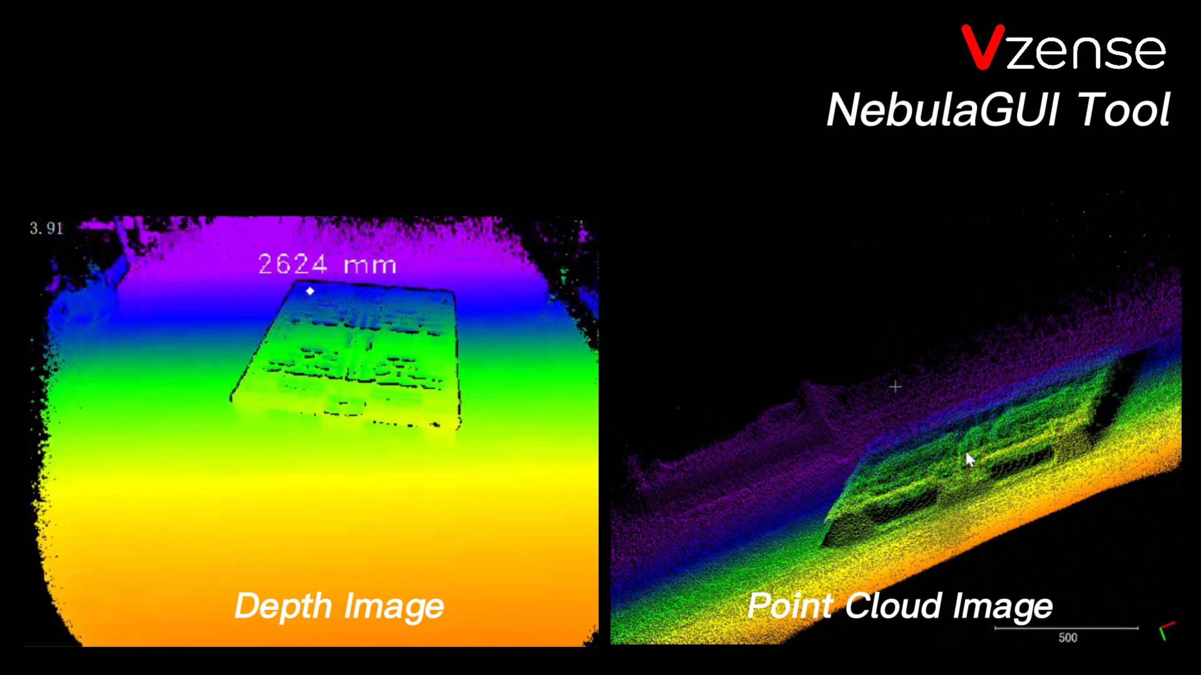
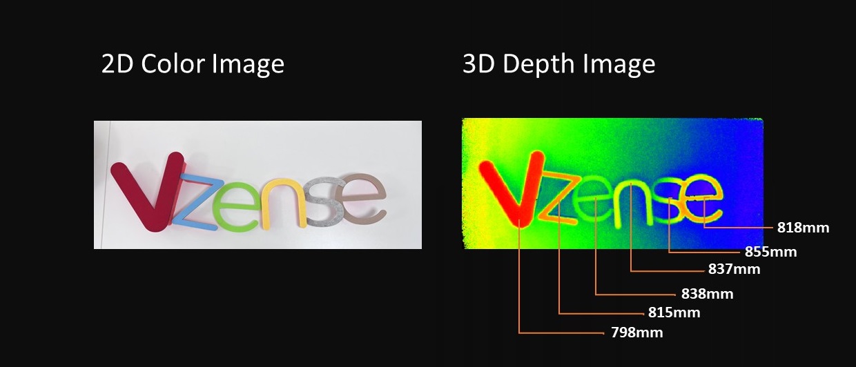
As shown in the above figure, unlike the image taken by the left traditional color camera, the image displayed by the right stereo vision technology is composed of the distance from each pixel to the camera. In order to better present the difference in distance, different distance values are usually mapped to the color gamut space, so that users can more easily understand the meaning of depth images, as shown in the following figure:
The purpose and development direction of 3D vision technology is to obtain more accurate, more delicate and faster depth images through various methods.
Taxonomy and Principles of Distance Measurement
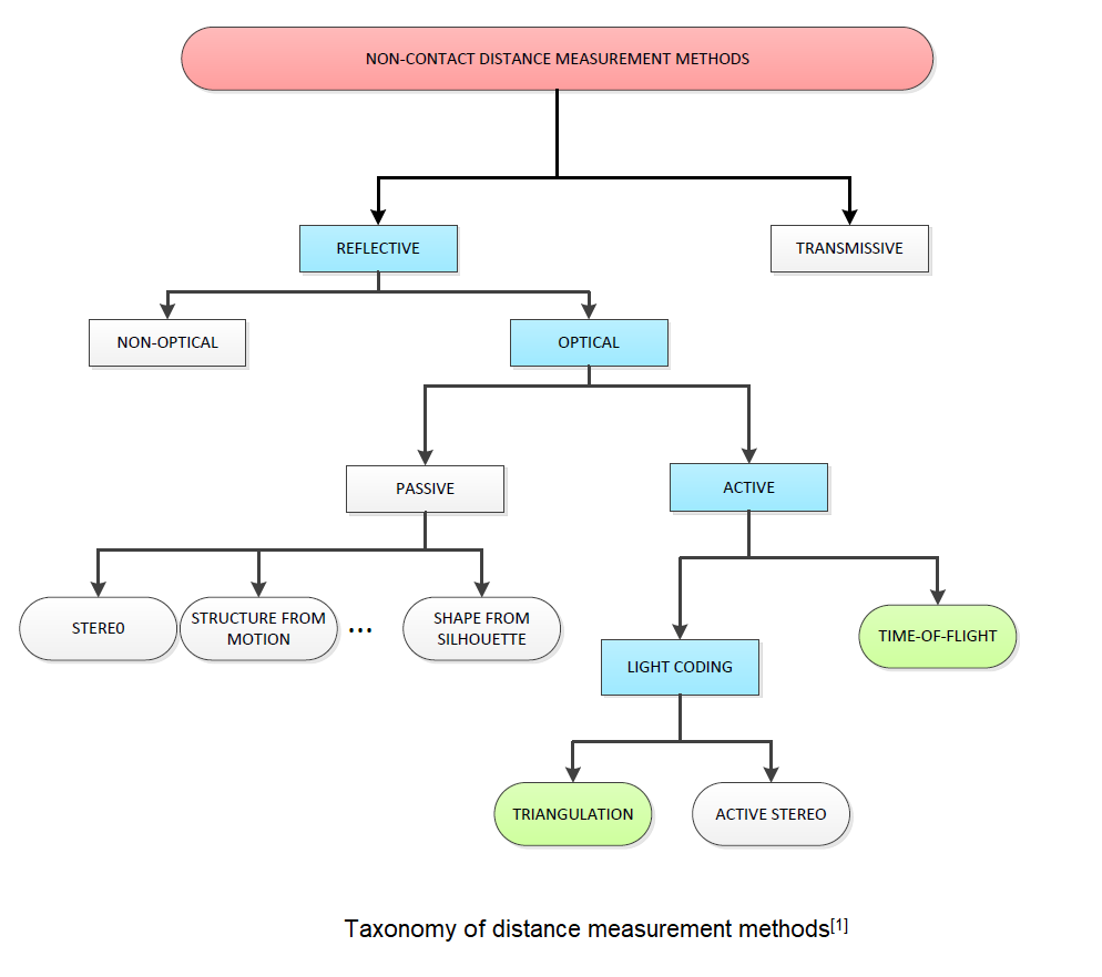
Reflective optical methods are classified into two main categories: passive and active.
Passive reflective optical methods typically rely on ambient light to measure the distance between a target surface and a detector. Stereo vision is an example of a passive reflective optical method that uses two cameras to capture images of a target surface and calculate the distance between the target surface and the cameras based on the relative positions of the cameras and the target surface.
A stereo vision system consists of two cameras positioned side by side, which capture two images of the same scene from slightly different angles to generate a 3D representation of the scene based on the information captured by the two cameras. To achieve this, the stereo vision system uses algorithms to identify corresponding points in both images, and then calculates the relative depth of different objects in the scene based on the differences in their positions in the two images. This process is known as triangulation. When there are no geometric or color features in the scene, the stereo images will be uniform, and there won't be any corresponding pixels to obtain depth information from triangulation. The system would not be able to perform stereo matching or depth estimation in such a scenario. This is why it's important to have well-textured scenes or to add artificial markers or features to the scene to perform stereo vision tasks. The additional information provided by these features allows the stereo system to perform triangulation and estimate the depth information of the scene.
Active reflective optical methods, on the other hand, do not rely on ambient light, but instead use a projected light source to obtain 3D range information. ToF camera and light coding system(or called structure light system) are examples of active reflective optical methods.
A ToF(Time-of-Flight) camera is a type of active depth sensing camera that measures the time it takes for light to travel from the camera to an object and back. By measuring the time delay, the TOF camera can calculate the distance of objects from the camera, and generate a depth map.
A structure light system uses a projected pattern of light (such as a stripe or checkerboard pattern) to determine the depth of objects in a scene. The pattern is projected onto the scene and the camera captures the deformed pattern as it falls onto the objects. By analyzing the deformation of the pattern, the depth information of the objects can be reconstructed to create a 3D representation of the scene.
Talking back to Time-of-Flight technology which Vzense has been dedicated on for years.
Time-of-Flight (TOF) technology generally refers to a family of methods for measuring the time it takes for a signal to travel from a source to a target and back. In the context of cameras, TOF cameras specifically use light to measure the time of flight, but there are other methods that use other types of signals, such as acoustic waves or electromagnetic waves. In all cases, the goal is to determine the time it takes for a signal to travel from the source to the target and back, which can then be used to calculate distance or other information.
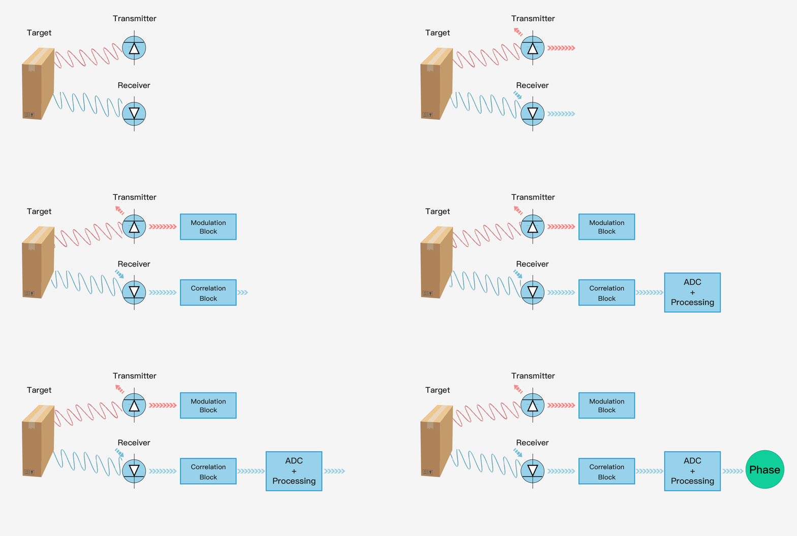
The simplest single pixel ToF technology uses a modulated collimating laser as the transmitter and a single optoelectronic diode as the receiver, which can be used to provide the distance information of a single point. If you want to use a single pixel distance sensor to provide the depth map of the entire scene, it will generally use some scanning form. The following figure shows the principle of single pixel ToF ranging technology.
3D ToF technology provides a complete scene depth map through one-time imaging, without scanning devices. With the shrinking size of semiconductor components, the compact, cost-effective ToF depth camera has been rapidly applied and developed in the industrial and consumer electronics fields.
Components of a ToF Camera
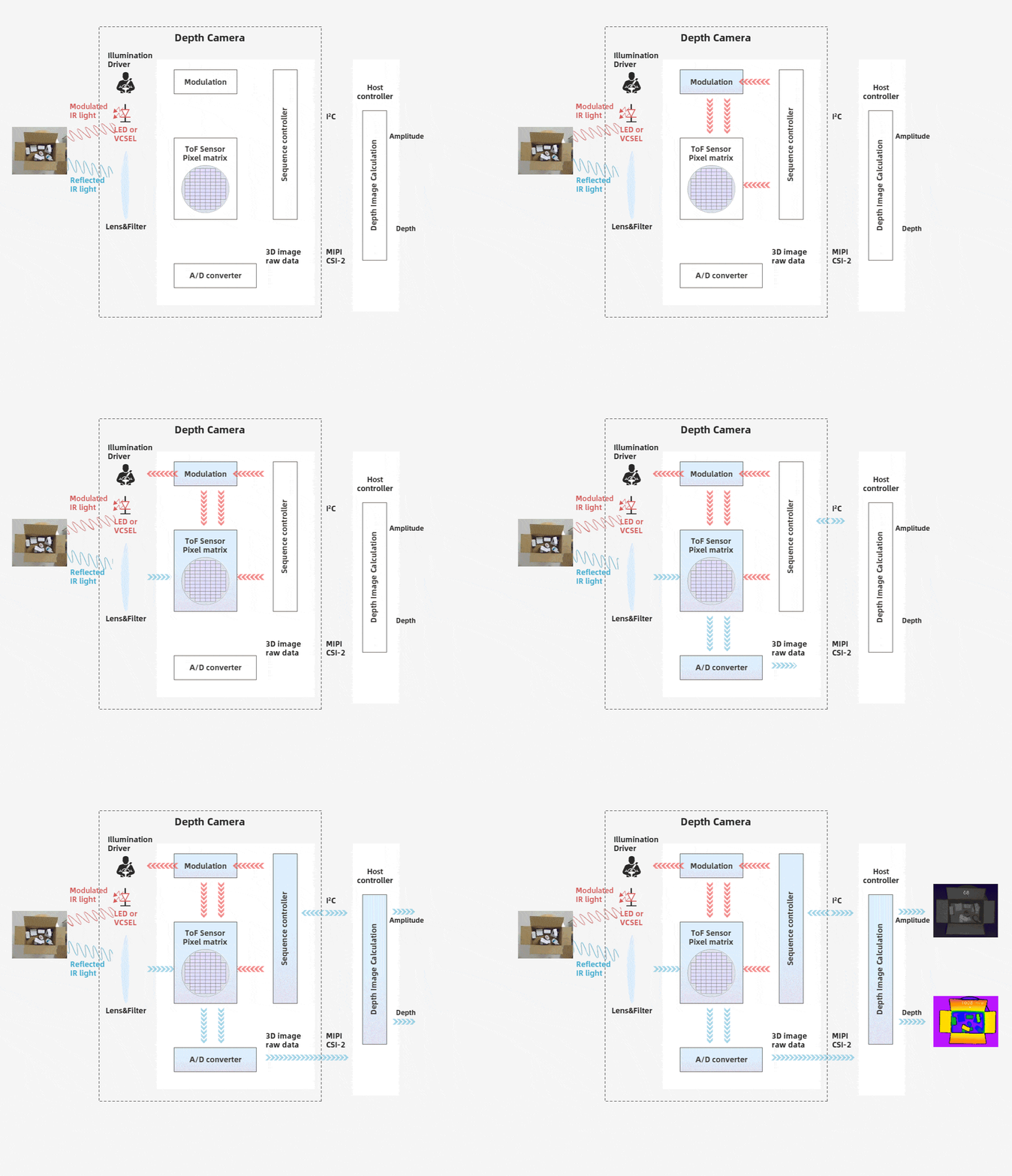
The ToF camera refers to the area array non scanning 3D imaging depth information capture technology with the optical system as the receiving path. From the following figure, we can understand that the ToF depth camera is composed of an irradiation unit, an optical lens, an imaging sensor, a control unit, and a computing unit.
- Irradiation unit
The irradiation unit needs to pulse modulate the light source before transmitting, and the modulated light pulse frequency can be as high as 100MHz. Therefore, in the process of image shooting, the light source will be turned on and off thousands of times, and each light pulse only lasts for a few nanoseconds. The exposure time parameter of the camera determines the number of pulses for each imaging.
In order to achieve accurate measurement, it is necessary to precisely control the light pulse so that it has the same duration, rise time and fall time. Because even a small deviation of 1ns can produce a distance measurement error of up to 15 cm. Such high modulation frequency and accuracy can only be achieved by using sophisticated LED or laser diode.
Generally, the infrared light source that is invisible to the human eye is used.
- Optical lens
It is used to gather reflected light and image on the optical sensor. Unlike ordinary optical lenses, a band-pass filter is required to ensure that only light with the same wavelength as the illumination light source can enter. The purpose of this is to suppress the incoherent light source to reduce noise, and prevent the overexposure of the light sensor due to the interference of external light.
- Imaging sensor
The imaging sensor is the core of TOF camera. The structure of this sensor is similar to that of an ordinary image sensor, but more complex than that of an image sensor. It contains two or more shutters to sample reflected light at different times. Therefore, the pixel size of TOF chip is much larger than that of ordinary image sensors, generally about 100um.
- Control unit
The light pulse sequence triggered by the electronic control unit of the camera is precisely synchronized with the opening/closing of the electronic shutter of the chip. It reads and converts sensor charges and directs them to the analysis unit and data interface.
- Calculation unit
The calculation unit can record accurate depth map. The depth map is usually a grayscale image, where each value represents the distance between the light reflecting surface and the camera. For better results, data calibration is usually performed.
Direct ToF vs Indirect ToF
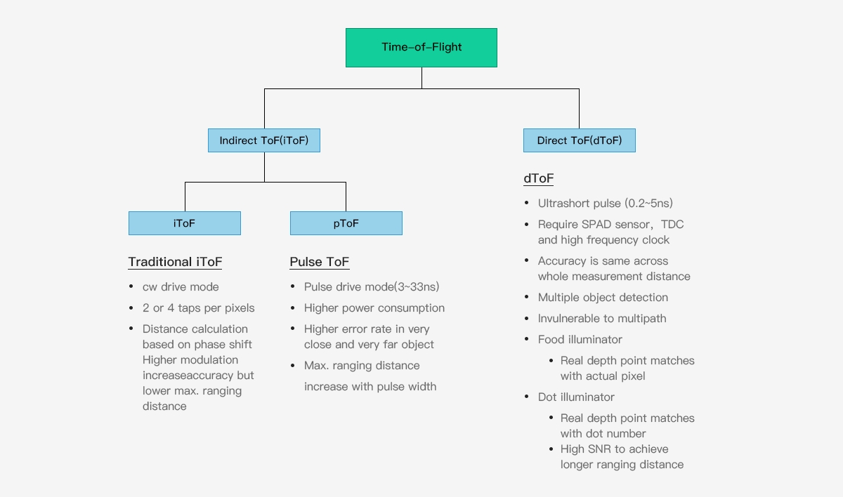
ToF 3D camera technology can be divided into iToF (indirect ToF) and dToF (direct ToF) according to the specific implementation method. IToF is further divided into Continuous Waveform ToF and Pulse Based ToF, as shown in the figure below:
dToF
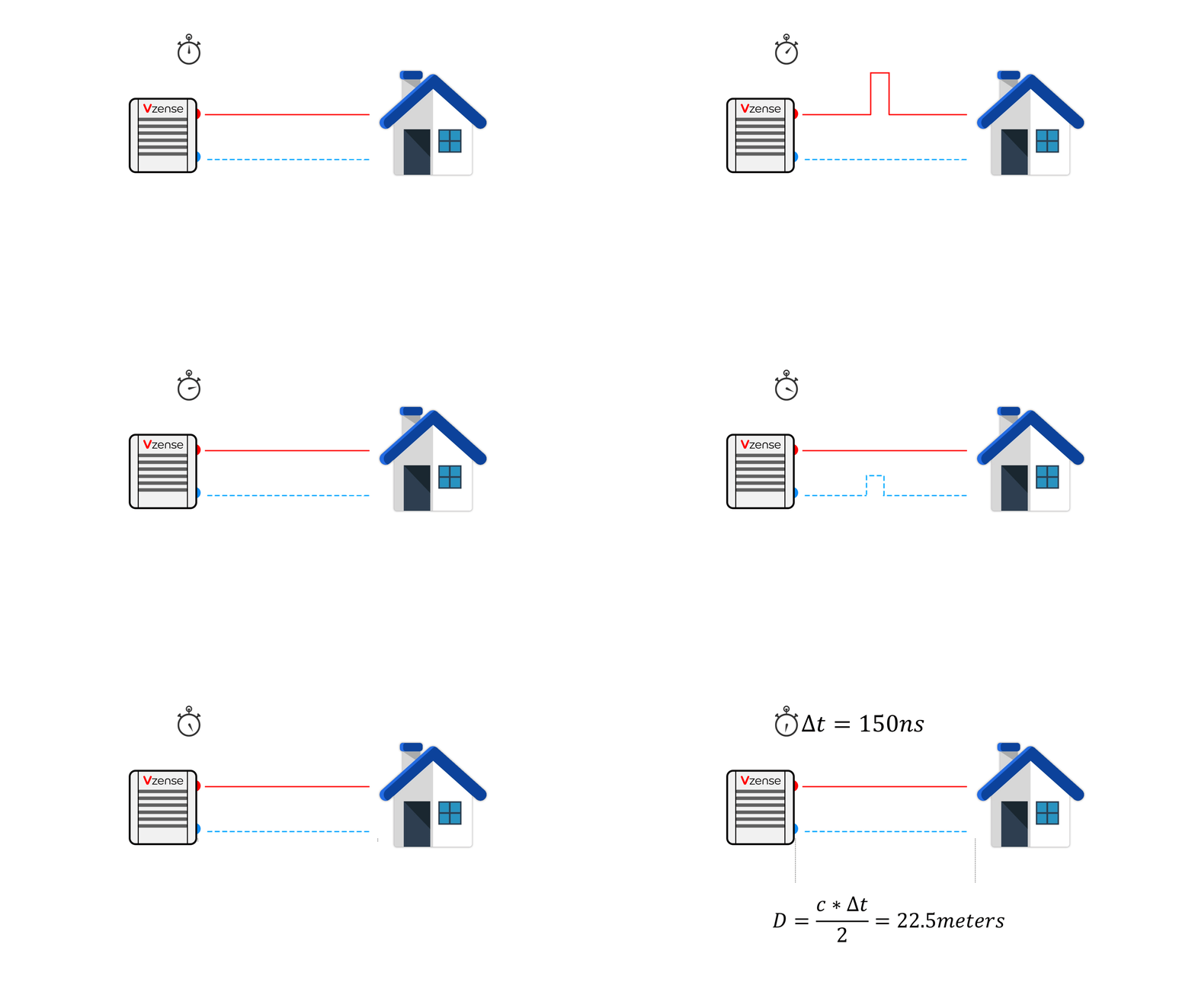
DToF (direct time of flight), which is a direct time of flight ranging method, directly measures the time difference between the time tstart when the laser pulse is sent from the transmitting end and the time tstop when the laser pulse returns to the receiving end after being reflected by an object by means of an internal timer. In combination with the speed of light c, the distance depth data d is obtained. Compared with the method mentioned below, which indirectly measures the time difference between the transmitting signal and the receiving signal through the signal phase difference, This method of measuring time difference is more direct, so it is called direct time of flight ranging method.
The principle of direct time-of-flight ranging is direct and simple, but the technical level has high requirements for the light source at the transmitter, the image sensor at the receiver, and the circuits related to synchronization and time detection. For example, there are certain requirements for the transmitter to generate such short pulses, and the image sensor at the receiver also needs to use highly sensitive optical detection technology to detect weak optical signals, such as single photon avalanche diode (SPAD) technology.
CW iToF
The basic principle of CW iToF is to adjust the light into a sine wave with a fixed frequency f, and the transmitting end transmits the sine wave according to the frequency f. When collecting the returned optical energy, CW iToF will open multiple windows, sample the data collected by multiple windows, analyze the phase difference information between the transmitting and receiving within a period, and then obtain the distance information through the following formula.
>>> Click to view CW iToF products
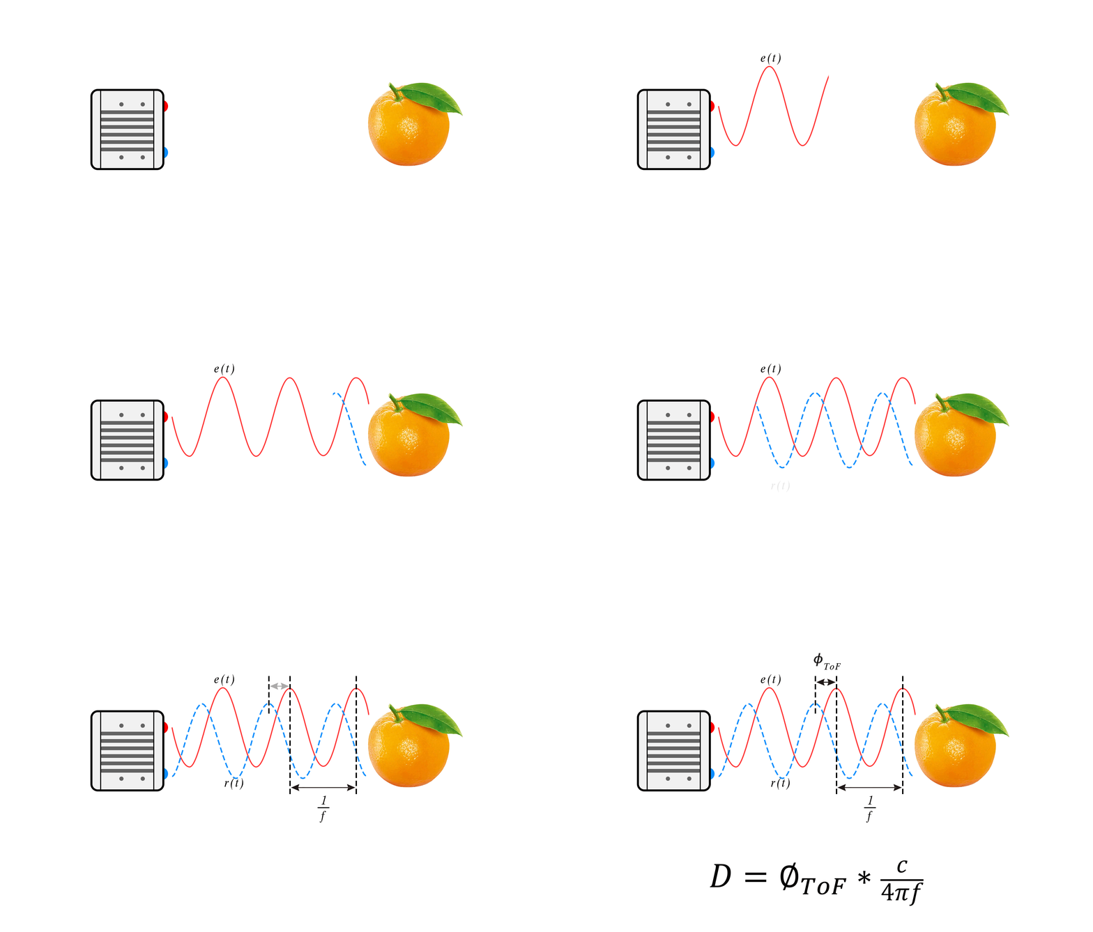
The vast majority of continuous waveform ToF systems use CMOS sensors, especially the back illuminated CMOS process technology, which greatly improves the light-sensitive area, photon collection rate and ranging speed, and the response time can reach the level of ns; To realize phase unwrapping, CW ToF will apply multiple modulation frequencies - this method will be very helpful to reduce multipath errors; CW iToF is a full CMOS imaging system, which has better flexibility and faster readout speed. However, CW iToF method also has some disadvantages. Its image sensor requires four samples of correlation function at multiple modulation frequencies, plus multiple frame processing, so the complexity of signal processing will become higher, which may require additional application processors; For longer distance measurement, or when the ambient light in the scene is strong, the continuous output power requirements are high, which will affect the heating and stability.
Pulse iToF
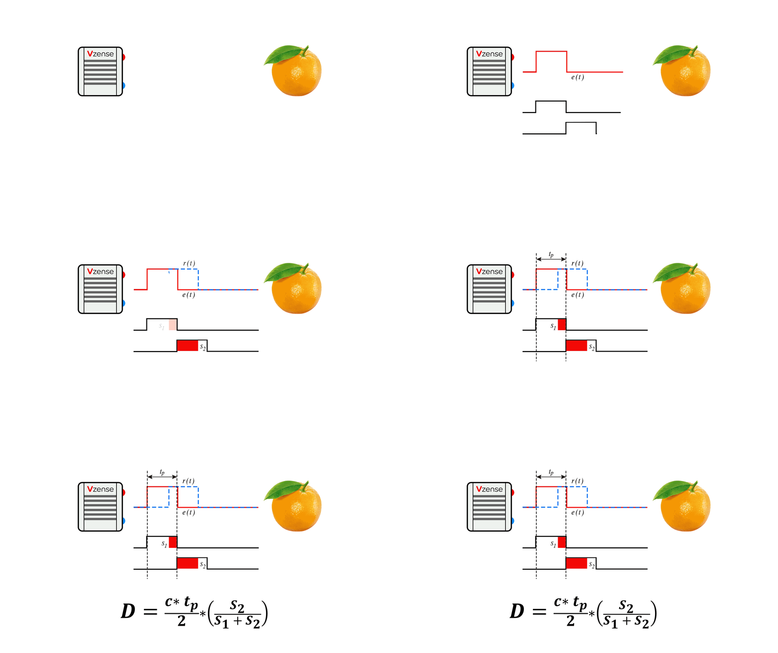
The following figure is a schematic diagram of the principle of Pulse iTOF. By adjusting the light into a square wave with a fixed frequency f, the transmitting end transmits pulse signals according to the frequency f. The sensor at the receiving end consists of two electronic shutters (s1, s2). The frequency and phase of the S1 window are consistent with the transmitting pulse. When the S1 and S2 windows are opened (high electrical level), they accumulate photons reflected from the object within their respective time. By calculating the different energy value proportions of s1 and s2, The signal phase is analyzed to calculate the time difference between the transmitted signal and the received signal, and then the distance data is obtained.
Compared with CW iToF continuous wave debugging mode, Pulse iToF has simpler solution depth, lower computational load, and lower requirements for back-end processing capacity of the platform. From the principle of Pulse iTOF, Pulse iTOF emits high-intensity light pulses in a short time window, which can reduce the impact of background light signals, make it more adaptive to changes in ambient light, and better resist problems such as scene motion blur.
>>> Click to view pulse iToF products
Different Technology Comparison
| Stereo | Speckle Structured Light | Striped Structured Light | iTOF | dTOF | LiDar | |
|---|---|---|---|---|---|---|
| Accuracy | High at near place | High at near place | High | Linear with distance | Fixed error | Sub-millimeter |
Detection distance | Near | Near | Near | Medium near | Medium far | Medium far |
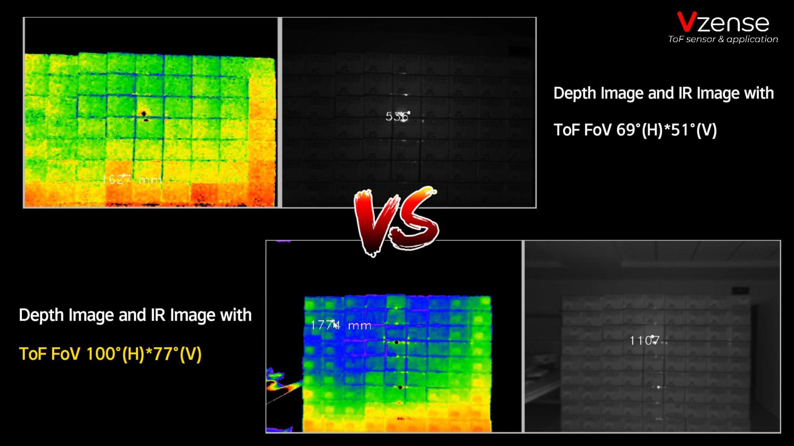
| FoV | Medium | Medium | Medium | Big | Big | Low |
| Frame rate | High | Medium | Low | High | Medium | Medium |
| Resolution | Medium | Medium | High | Medium | Medium | Low |
| Cost | Low | Medium | High | Medium | High | High |
Light influence | Low | High | High | Low | Low | Low |
The advantages of ToF technology are shown in multiple dimensions, including detection range, angle, frame rate, light resistance, cost performance, etc; The ToF technology has great advantages in scenes where the accuracy is required to be above the mm level.
Applications
Visual Positioning and Guidance
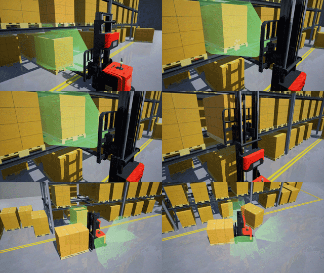
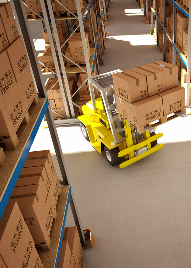 AGV
AGV
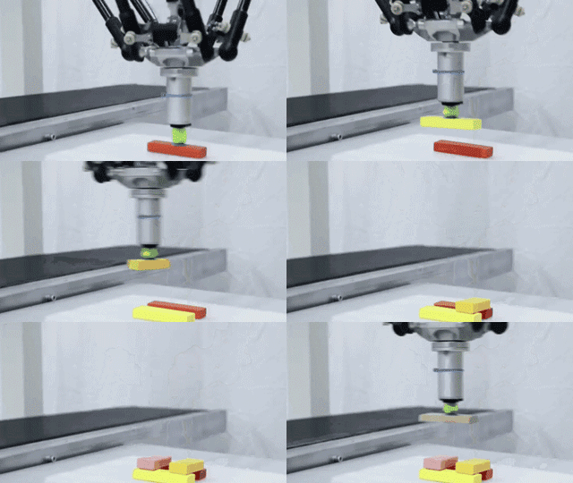
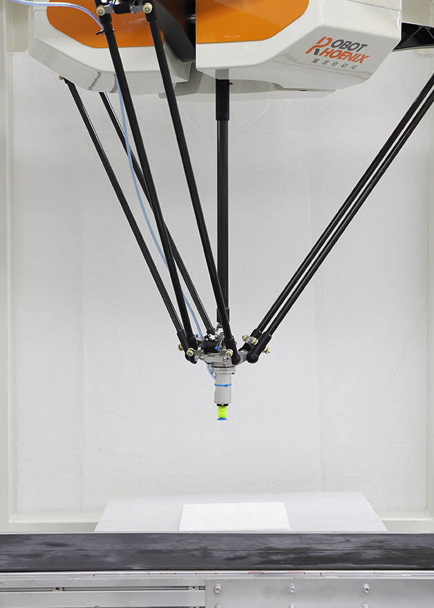 Visual Control for Delta Robot
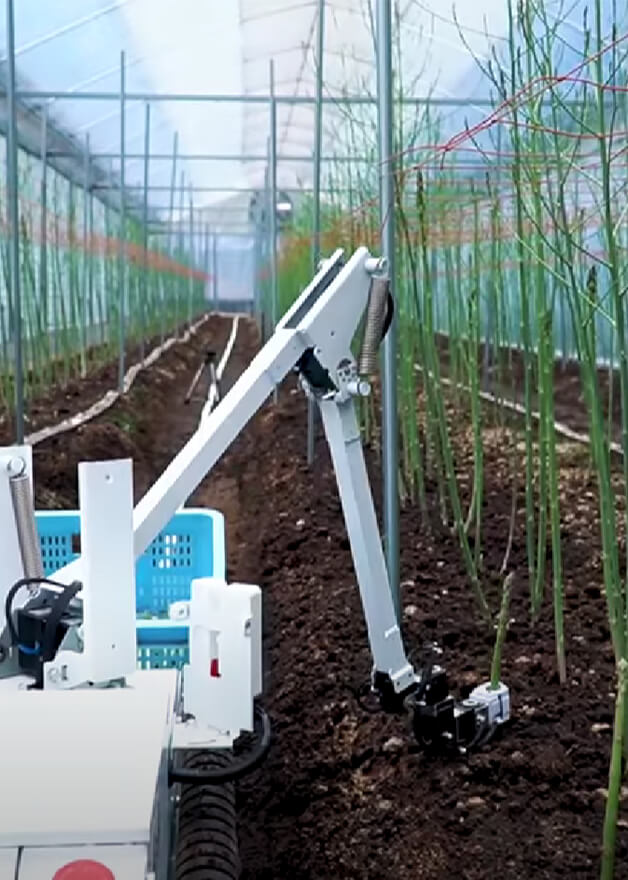 Smart Agriculture
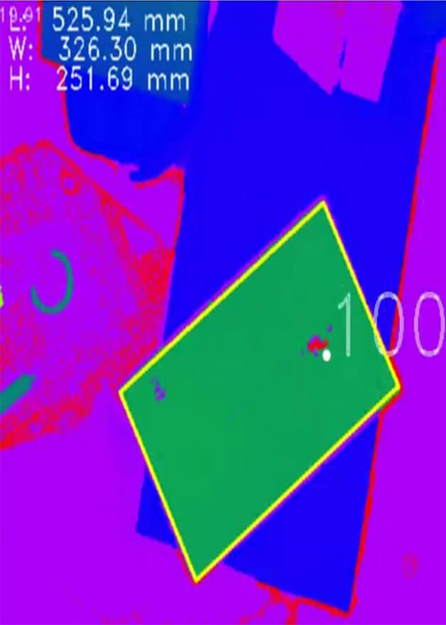 Dimension Measurement
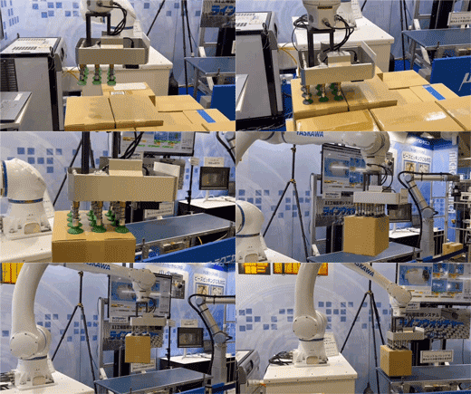
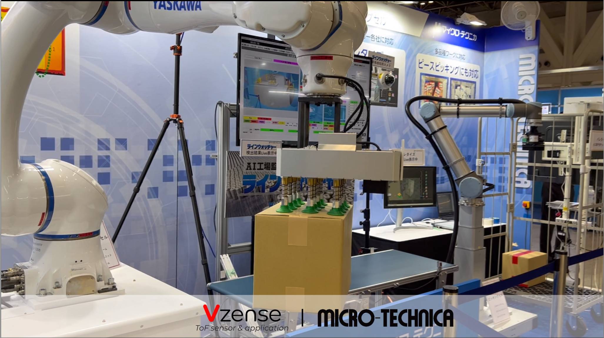
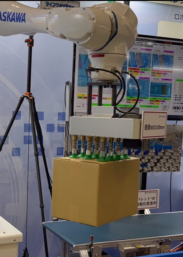 Palletizing and Depalletizing
Gesture Capture and Behavior Recognition
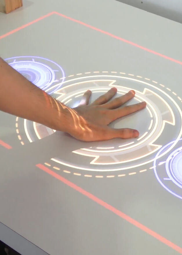 Interaction
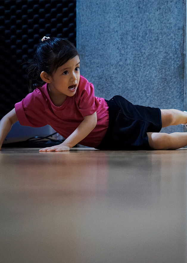 Fall Detection
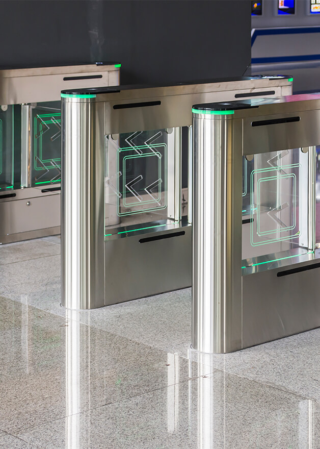 Automated Fare Collection
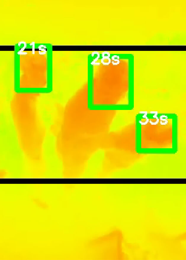 People Counting
Videos
Application Collection
Performance Demonstration


 EN
EN







.png)
.jpg)

.png)
.png)

.png)
